模板图像与对齐理论
本页面解释基于模板的模式匹配背后的基本概念,以及 OV20i 如何使用边缘检测算法来定位并定向部件,以实现精确的检查定位。
基于模板的模式匹配基础
什么是模板对齐?
模板对齐使用模式匹配来定位和定向部件,以进行相对检查。系统在模板区域内检测边缘,并匹配相似的边缘模式以确定部件的位置和朝向,即使在部件呈现方式不一致时也能实现准确检查。
核心概念:
- Reference Template - 捕获的图像,作为模式匹配的基线
- Edge Pattern Recognition - 算法识别显著的边缘特征
- Spatial Transformation - 计算位置及旋转差异
- ROI Adjustment - 相对于检测到的部件位置对检查区域进行对齐
模板图像理论
模板图像作为参考标准
捕获模板图像是 ALL 配方的必需步骤。模板图像作为主参考,用于与后续图像进行比对以实现对齐。
模板要求:
- Representative Sample - 必须显示处于理想条件和位置的部件
- Clear Edge Definition - 充足的对比度以实现可靠边缘检测
- Consistent Features - 在部件变体之间保持稳定的特征
- Optimal Lighting - 照明条件应与生产环境相匹配
图像质量对对齐的影响
关键质量因素:
- Edge Contrast - 更高对比度可实现更可靠的边缘检测
- Focus Sharpness - 清晰的边缘提升模式匹配的准确性
- Lighting Consistency - 均匀照明可减少错误的边缘检测
- Image Stability - 模板图像中的噪声和伪影应降至最低
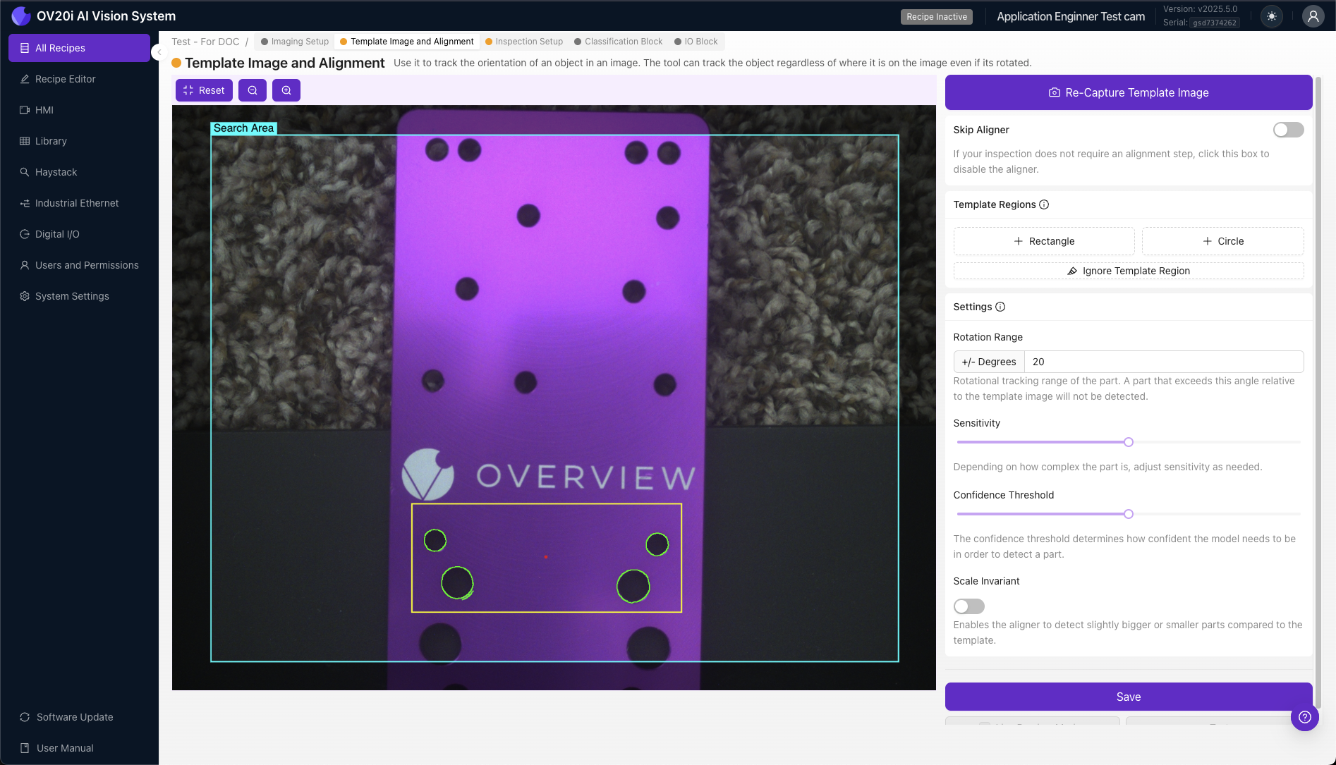
模板图像设置与捕获
模板图像捕获方法
捕获选项:
- Capture Template Image - 使用当前相机视图拍摄新的参考图像
- Re-Capture Template Image - 用新图像替换现有模板
- Import From Library - 从库中选择现有图像作为模板
默认情况下,从 Library 导入模态框将按 Recipe 过滤图像。使用下拉菜单选择另一个 recipe,或清除筛选并单击 Search 以在其他 Recipes 中查找图像。
预览模式
- Template View - 捕获后,预览窗格显示模板图像(非实时相机)
- Live Preview Mode - 切换到实时相机视图以测试对齐性能
- Re-capture Mode - 关闭实时预览以重新捕获模板图像
对齐理论的边缘检测
对齐特定边缘检测
OV20i 对齐系统依赖于专门用于部件定位和定向的边缘检测算法,与基于 AI 的检测模型分离。
对齐边缘检测过程:
- Edge Identification - 算法检测用于对齐参考的强度梯度
- Edge Filtering - 系统在过滤噪声的同时识别与对齐相关的边缘
- Alignment Pattern Creation - 构建用于定位的边缘模式的数学表示
- Position Comparison - 将检测到的模式与模板参考进行对齐对比
Alignment Region Strategy
+ Rectangle / + Circle Regions: Template Regions define specific areas where the OV20i will detect edges for alignment purposes, matching similar edge patterns to determine part position and orientation.
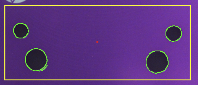
Alignment Edge Visualization:
- 🟢 Green Highlights - Edges found inside Template Region (suitable for alignment)
- 🔴 Red Highlights - Insufficient edges found for valid alignment
Edge Quality for Alignment
Good Alignment Edge Characteristics:
- Simple - Clear, well-defined edge transitions suitable for position reference
- Unique - Distinctive patterns for reliable part identification
- Consistent - Visible across all expected part variations for reliable alignment
- Stable - Not affected by normal production variations during alignment
Poor Alignment Edge Characteristics:
- Complex Textures - Detailed surfaces unsuitable for position reference
- Reflective Surfaces - Areas creating inconsistent alignment references
- Variable Features - Elements that change between parts, affecting alignment consistency
- Noise-Prone Areas - Regions with debris affecting alignment accuracy
Template Regions Management
Creating Template Regions
+ Rectangle / + Circle: Click to add a Template Region to the Template Image. The OV20i will detect edges inside these Template Regions and try to locate parts by matching similar edge patterns.
Region Management:
- Resize/Reshape - Click on Template Region to stretch or change size
- Rotate - Adjust region orientation as needed
- Reposition - Click and drag to move Template Region
- Delete - Remove unwanted regions
Template Region Placement Best Practices
When placing Template Regions, focus on edges that are simple, unique, and consistently visible across all parts. Try to avoid edges that may be obscured by defects, or edge patterns that vary from part to part.
Good Edge Characteristics:
- ✅ Simple - Clear, well-defined edges
- ✅ Unique - Distinctive patterns not found elsewhere
- ✅ Consistent - Visible across all part variations
- ✅ Stable - Not affected by normal defects or wear
Poor Edge Characteristics:
- ❌ Variable features - Components that may be missing or damaged
- ❌ Textured surfaces - Complex patterns that vary part-to-part
- ❌ Reflective areas - Surfaces that create variable highlights
- ❌ Small details - Features easily obscured by debris
Progressive Setup Approach
Multiple Template Regions Strategy:
- Start with one Template Region on most prominent feature
- Add additional regions if edge count is insufficient (red highlights)
- Increase sensitivity if needed to find adequate edges
- Use Ignore Template Region tool to remove noise
- Test with Live Preview Mode across part variations
Alignment Parameter Theory
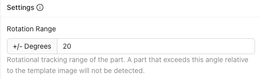
Rotation Range Tolerance
Enter an angle of 0-180 degrees to define the amount of rotation the aligner will tolerate.
Rotation Range Settings:
- 180 degrees - Find parts rotated at any angle (maximum flexibility)
- 0 degrees - Find only parts that match Template Image angle (maximum precision)
- Custom range - Balance between flexibility and precision
Trade-offs:
- Wider range - More flexible but potentially slower processing
- Narrower range - Faster processing but requires consistent part orientation
边缘查找灵敏度算法理论
通过滑块调整来增加/减少边缘查找灵敏度。更高的灵敏度设置能够检测到更多边缘,而较低的灵敏度设置则检测较少边缘。
灵敏度影响:
- 更高灵敏度 - 能检测到更多边缘细节,但可能包含噪声
- 较低灵敏度 - 侧重显著边缘,但可能错过微小特征
- 最佳设置 - 仍能找到充足边缘的最低灵敏度

算法行为:
对齐边缘检测算法会根据灵敏度设置调整阈值,从而影响哪些强度梯度被归类为用于对齐的边缘。
置信度阈值理论
使用此滑块设置将对齐被视为有效所需的最低置信度(1% 表示完全匹配)。该阈值应处于 0.6-0.9 之间,以实现一致的对齐。
置信度计算:
- 对齐模式相关性 - 模板与检测到的对齐模式之间的数学相似性
- 几何一致性 - 用于定位的边缘特征之间的空间关系准确性
- 对齐边缘质量 - 用于定位参考的检测边缘模式的强度和清晰度
阈值指南:
- 0.6-0.9 范围 - 建议用于实现一致的对齐性能
- 更高数值 - 更严格的匹配,减少误报
- 较低数值 - 更宽松的匹配,可能接受较差的对齐

对齐噪声管理理论
用于对齐的忽略模板区域
Ignore Template Region 工具提供一个笔刷界面,用于从任意模板区域擦除不需要的边缘,以屏蔽不需要的边缘噪声,并将对齐聚焦在清晰、可重复的边缘模式上。
对齐边缘噪声类别:
- 纹理表面 - 复杂图案,不适合作为一致的对齐参考
- 反射与眩光 - 受光照变化影响,影响对齐精度
- 碎屑或污染 - 暂时性特征,不适合作为定位参考
- 可变组件 - 可能缺失或损坏的特征,影响对齐一致性
对齐噪声过滤策略:
- 选择性屏蔽 - 去除可变边缘模式,同时保留稳定的对齐特征
- 模式简化 - 将对齐算法聚焦在最可靠的边缘信息上
- 一致性优化 - 提高在不同部件变化下的对齐可靠性
对齐模式匹配性能理论
用于对齐的多模板区域
增加更多的模板区域会增加对齐的边缘数量,从而提高对齐模式匹配的可靠性和特异性。
多区域对齐的好处:
- 对齐冗余 - 多个参考点提升对齐鲁棒性
- 定位特异性 - 更复杂的模式减少误报的对齐匹配
- 对齐准确性 - 额外约束提升位置和旋转的精度
- 对齐可靠性 - 某些区域被遮挡时系统仍可对齐
对齐失败模式
常见对齐失败模式:
- 对齐边缘信息不足 - 无法为可靠定位检测提供足够的模式信息
- 错误对齐正例 - 算法将不正确的特征用于定位
- 对齐检测不一致 - 对齐在某些部件上有效但在其他部件上失败
- 对齐置信度低 - 定位匹配低于可接受阈值
对齐优化解决方案:
- 对齐图案优化 - 选择更具辨识度且更稳定的边缘特征用于定位
- 区域调整 - 修改模板区域的大小和放置位置以获得更好的对齐参考
- 参数调优 - 调整对齐性能的灵敏度与置信阈值
- 对齐噪声降低 - 使用 Ignore Template Region 工具来过滤有问题的边缘
Alignment vs Fixed Positioning Theory
When to Use Template Alignment
对齐的优势:
- 部件位置与旋转差异的容忍度 - 可容纳位置和旋转差异
- 灵活的呈现方式 - 适用于非夹具固定的部件
- 相对检查 - ROI 会自动根据部件位置进行调整
- 机器人集成 - 能处理可变部件放置
When to Skip Alignment
固定定位的优势:
- 处理速度 - 不需要对齐计算
- 结果一致 - 具有可预测的检测行为
- 简单设置 - 无需模板区域或模式匹配
- 对夹具固定的部件更可靠 - 当机械定位确保一致性时
选择标准:
对于夹具固定或对相机呈现非常重复性的部件的应用,建议跳过 Aligner 选项。